Intro
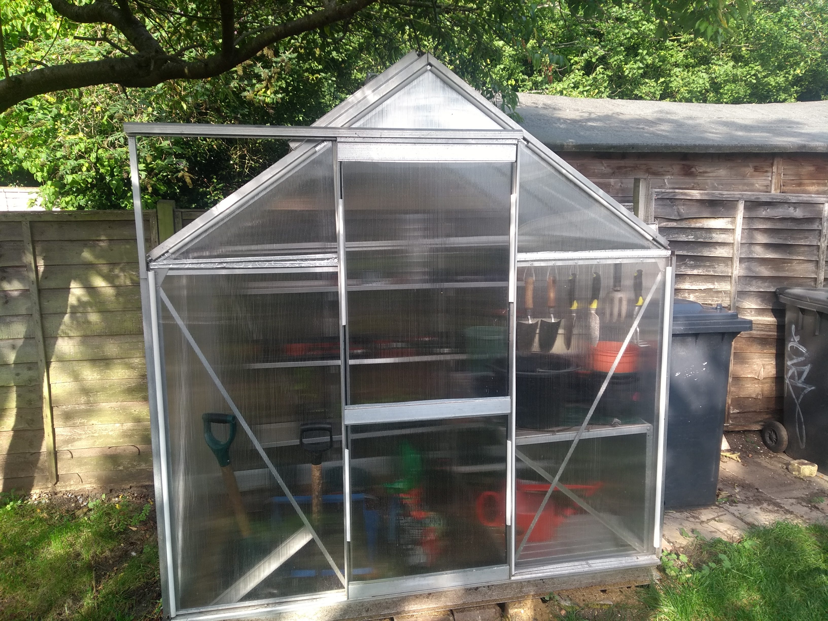
In this project I wanted to setup an automatic watering system for my new greenhouse. I also wanted it to collect lots of data and send it to my server (via unlicensed-band radio backhaul).
I used the extremely cheap and versetile ATTiny85 microcontroller.
Here are some links to the data & plotting pages
Radio
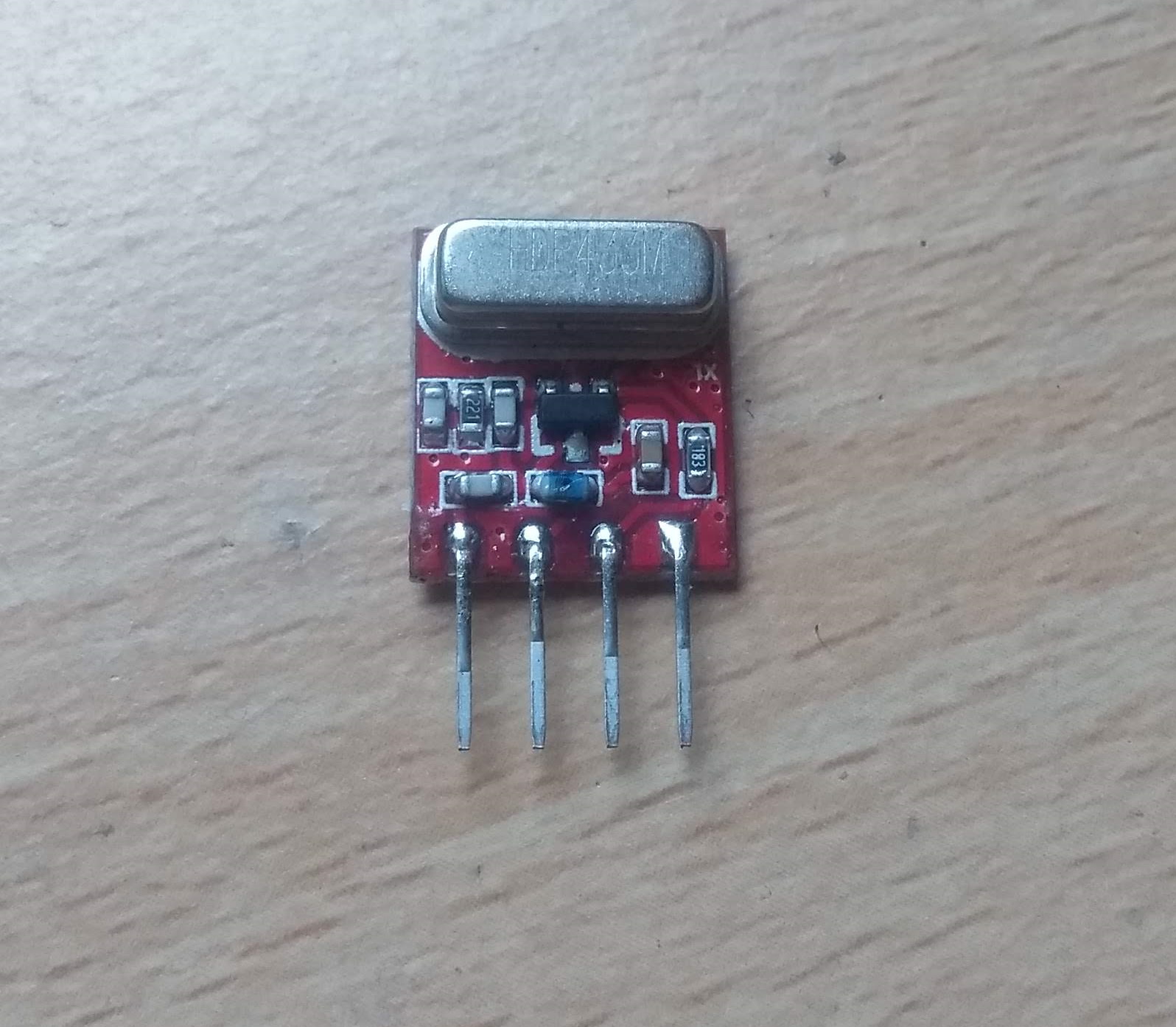
For the radio system I found some cheap 433MHz on off key (OOK) radio sets. I used the Quasar QAM-TX2.
OOK is a type of amplitude modulation (AM) - OOK is a binary modulation scheme with only two code words:
Signal present (ON)
Signal not present (OFF)
And that's it!
This is wrapped up into a frame packet consisting of: - Preamble
Packet length (N)
Device ID
Data x N
CRC
This is then picked up by a receiver powered by an Arduino Uno (as the ATTiny struggles with serial).
Antenna
I built a cheap quarter wavelength dipole antenna, 433mhz = 17.5cm arms.
The arms were then mounted to a frame (a coat hanger), and a suitable connector was wired in.

The antenna was connected using a poor mans SMA connector...
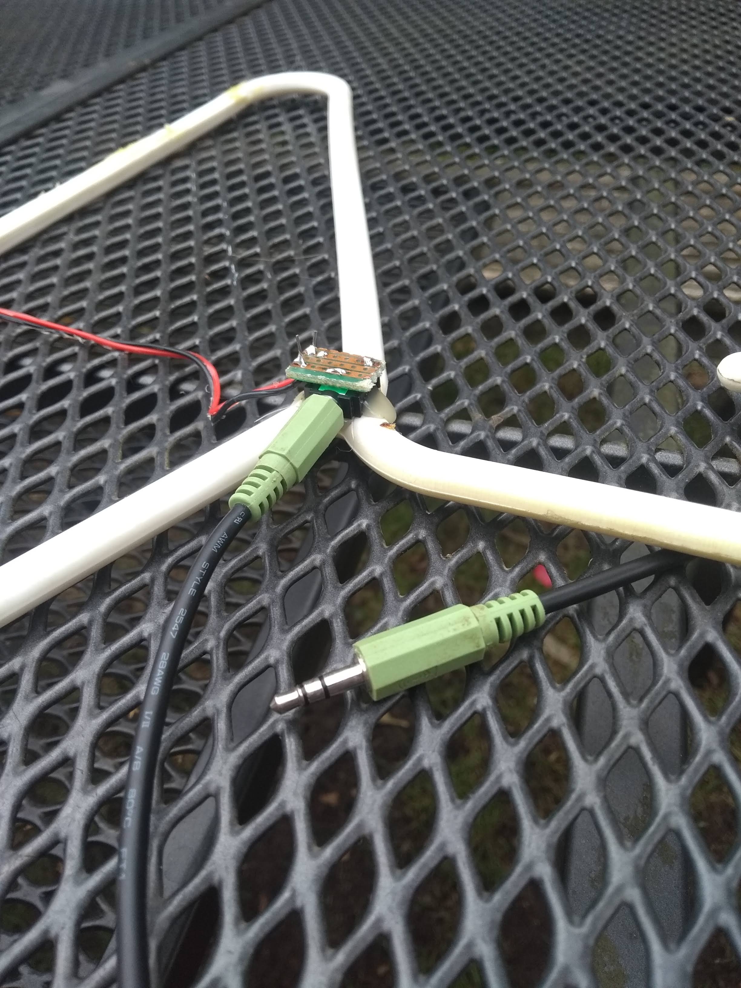
This greatly improved the receive power, sdr-sharp seems to think I have a 3dB SNR when all was said and done.
Sensors
The greenhouse has a couple of sensors
Light
Temperature
Humidity
Battery voltage
Water bucket
Light
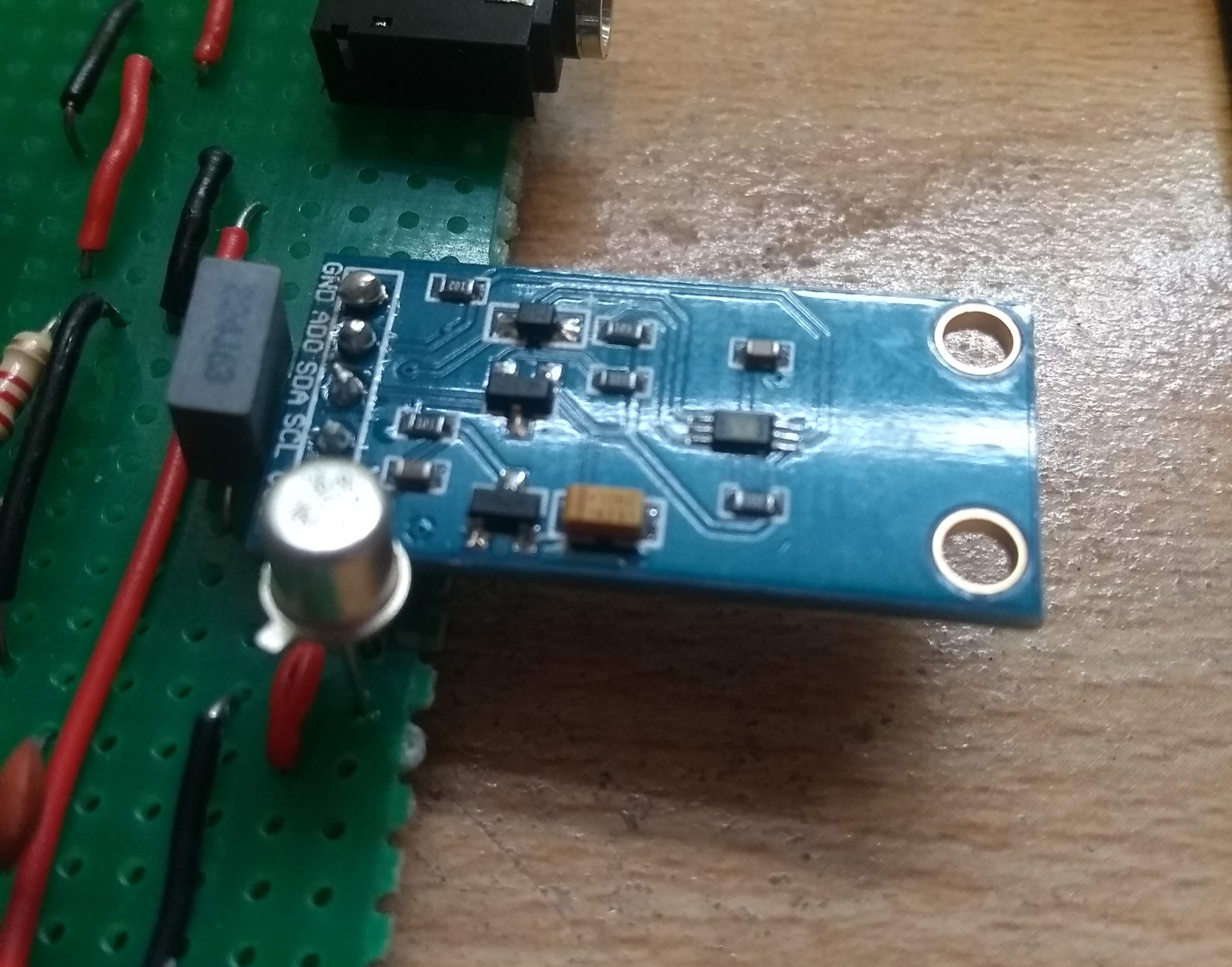
The light sensor is a pre-bought module, as most light sensors that are I^2C come in surface mount packaging. I would have had to buy an smt sensor, and a DIP adapter set and do the soldering myself.
In the end I bought the rather stylish: ALJIA GY-30 BH1750FVI Digital Light Intensity Sensor Module.
Temperature & humidity
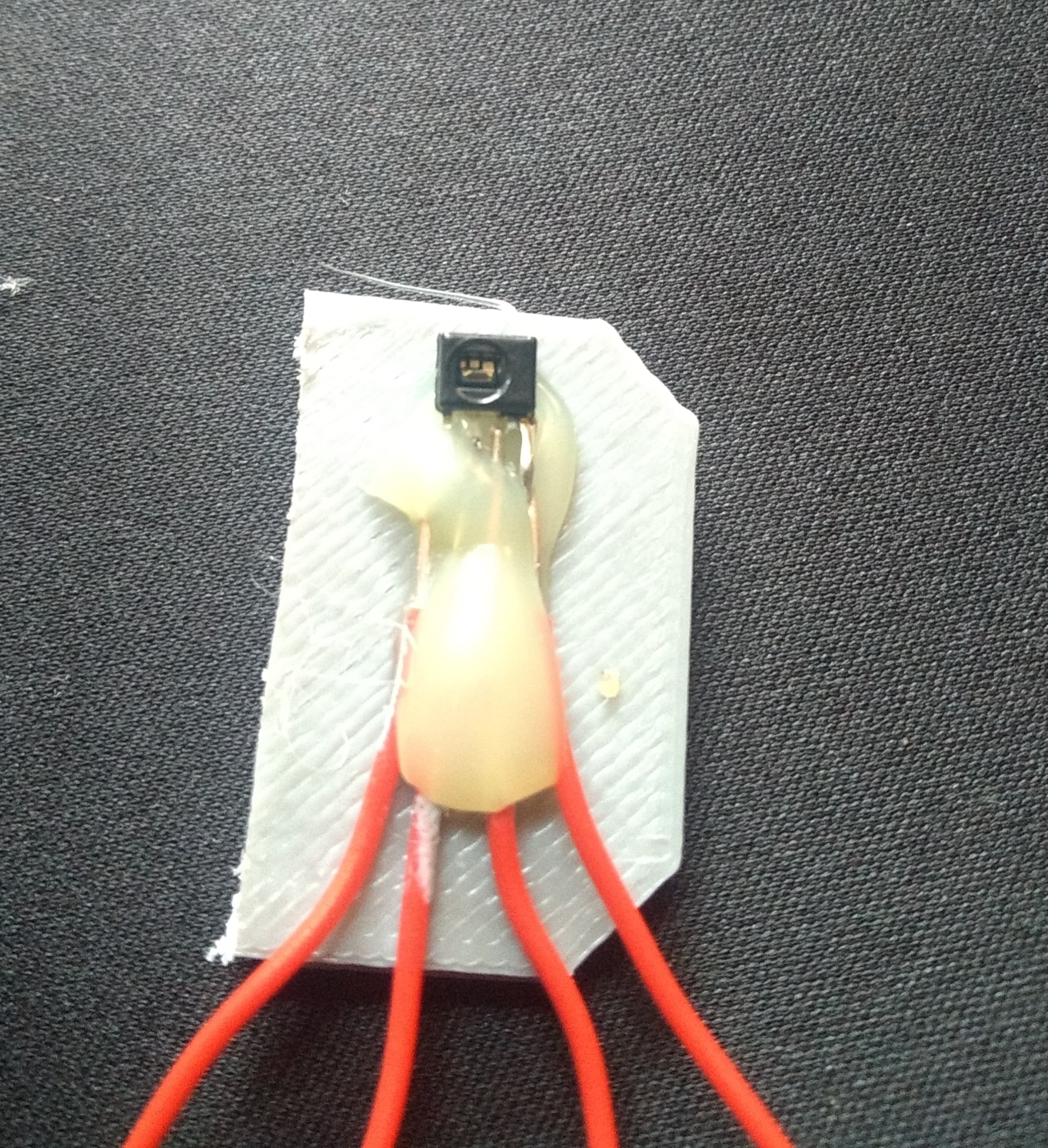
The temperature and humidity sensor is the Honeywell HIH-6120. The two sensors each have a 15 bit accuracy, and the device transmits it's data via an I^2C bus.
I accidentally bought a slightly small package - so I soldered the pins carefully and mounted it on some spare plastic:
Battery voltage
The battery voltage monitor uses the internal ADC and internal bandgap voltage reference. The ADC is configured to measure the fixed bandgap reference (~1.2v) with respect to the supply rail voltage.
This means the battery sensor is described by:
\[ V_{battery} = V_{bandgap} \cdot \frac{255}{B_{ADC}} \]Water bucket
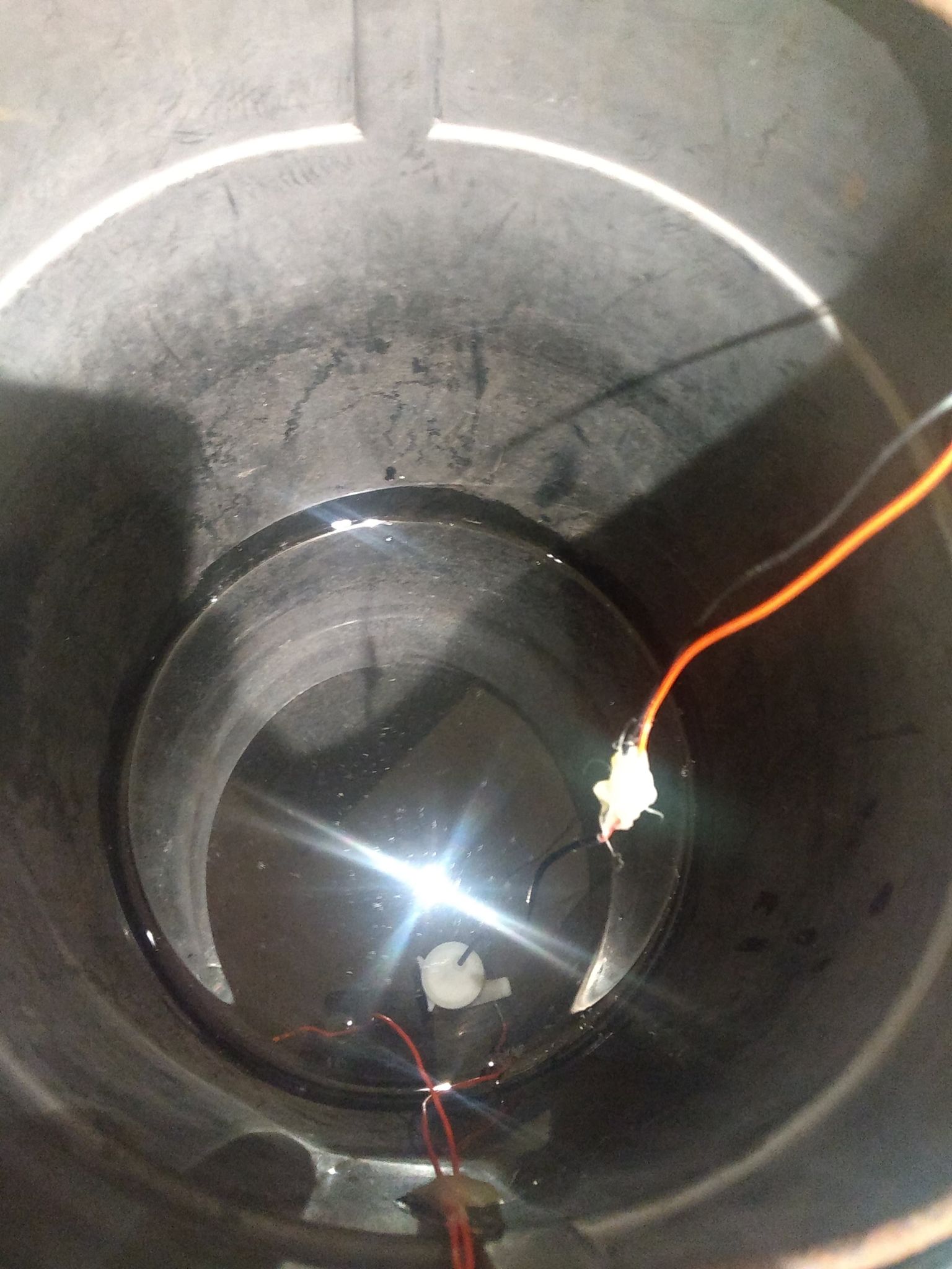
The water bucket sensor is a simple voltage divider that has one half of the bridge be two wires inside the bucket. When the water level is above a threshold the water "shorts" the terminals and forms a voltage divider. The tiny can read this as a digital voltage on one of it's pins.
Battery box
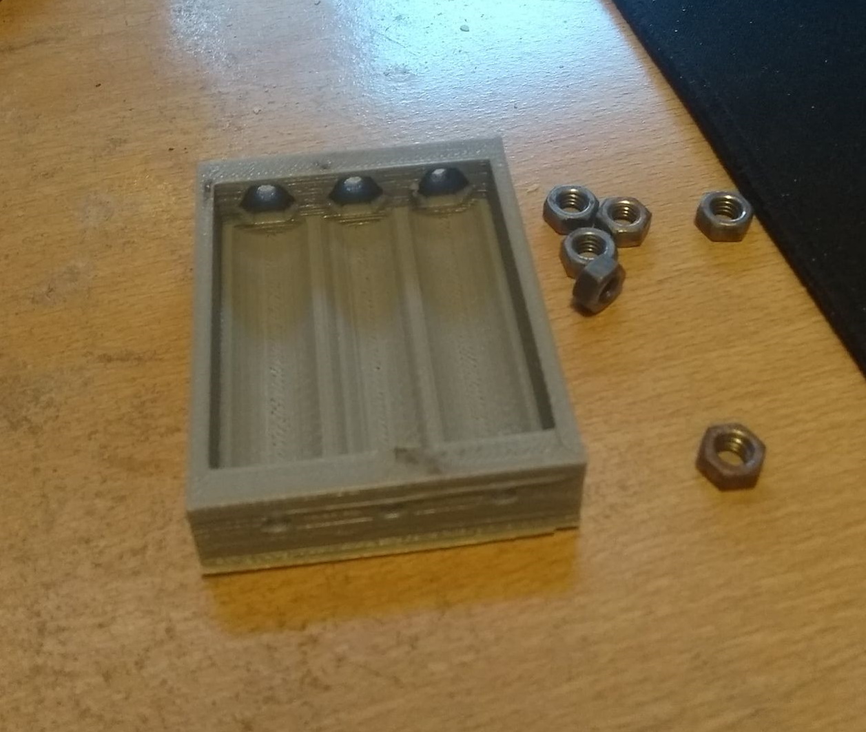
Since I didn't want to install a regulator, and the ATTiny is very forgiving in terms of VCC, I wanted to run directly from a battery. Unfortunatly the pump didn't want to operate off 2 AA batteries - and so I needed 3.
I got my brother to 3d print a battery enclosure - which I had to adapt a little to work
Pump
The pump was a small unlabeled dc motor. It wouldn't switch on with my transistor at 3.5v so it dictated the higher voltage.
The operation was very temperamental, it would often stop randomly.
I decided to put a \(0.1\mu F\) bypass capacitor to reduce high frequency line noise effecting the micro.
I also put a whopping big \(1500\mu F\) capacitor over the power rails, to carry over the dc surge current.

Final setup
For the final setup I soldered all the parts onto stripboard and mounted them in a spare plastic box from a takeaway.


Here is it installed in the greenhouse
